
Recently we had an interesting problem posed to us. The more general problem is detecting magnetization on a granular medium. Such questions are relevant for magnetic recording, e.g. tape, hard disk drives, etc.
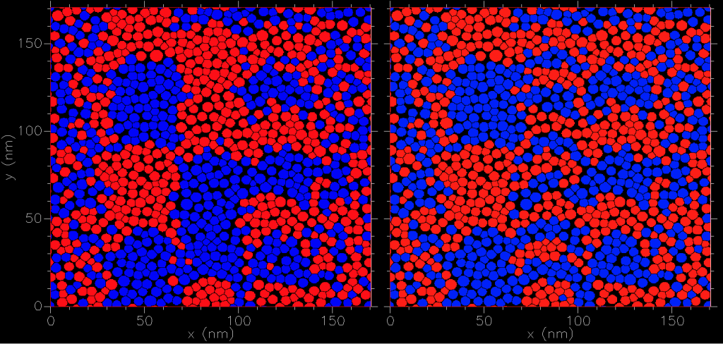
One can easily simulate a recording on futuristic granular storage medium. Here we take a fictitious medium for heat assisted magnetic recording (HAMR) of thickness 10nm and average grain diameter of 5.3nm at 83% packing. We write three tracks along the y direction (from top to bottom at 20m/s). The center track (x~85nm) is written followed by the two side tracks (each at 36nm offset). The only difference in these two results is the write frequency on the center track: low or high. Heat and write field profiles were identical along with the magnetic granular microstructure.
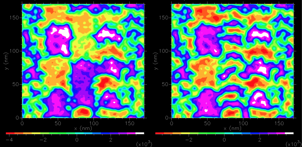
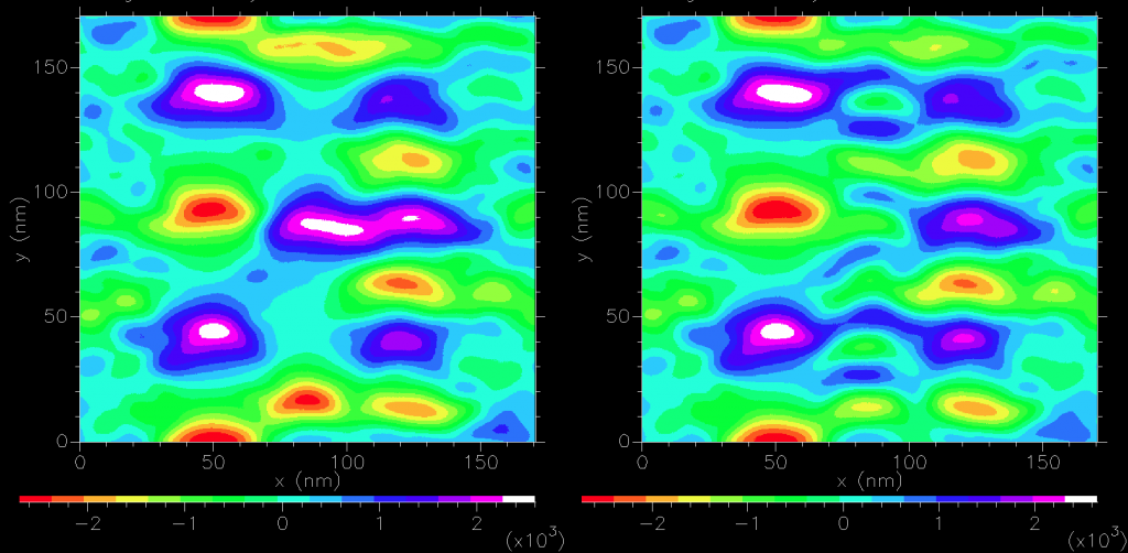
We can calculate the field generated by the magnetic medium. Sampling 3nm above the (periodic) medium we find for the normal component:
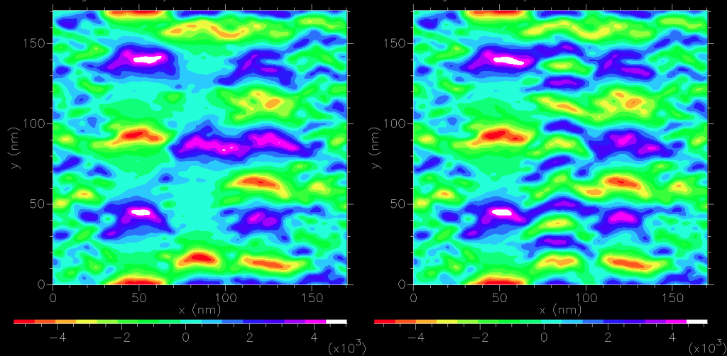
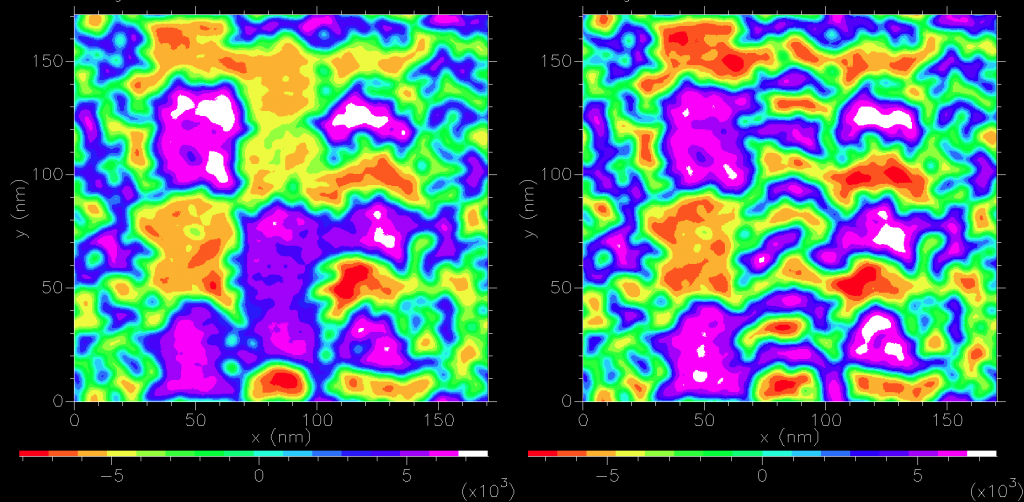
and for the downtrack component:
Since the size of the grain is similar to to the sampling plane distance, it is a poor approximation to assume dipole sources as confirmed by sampling 7nm above the medium
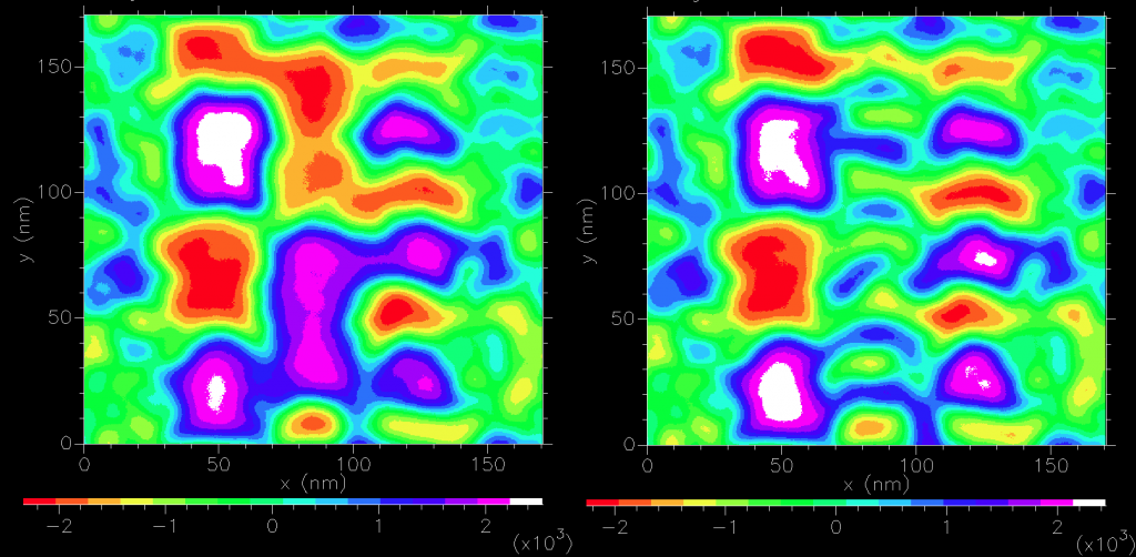
If we include a soft magnetic material (a poor approximation for ‘magnetic shields’- a typical feature of magnetic sensors), we see a doubling in the normal field produced while the in-plane field components are drastically reduced (not shown).
A typical magnetic sensor is predominately sensitive to the normal field component. In more elaborate calculations, Green’s second identity (commonly referred to as “reciprocity” in magnetic recording theory) is invoked to more easily calculate the signal. Here we are simply after an order-of-magnitude effect. The difference between the maximum and minimum normal field component would ideally map linearly to the magnetic sensor dynamic range. In reality, this rarely happens. Sensors are often characterized by dR/R, or the maximum change of resistance normalize by their minimum resistance. Either voltage or current through the sensor would then be the signal and would be directly proportional to the normal field. As the sensor size decrease the electronic noise (a.k.a. “mag noise”) becomes more important.
Before solid state magnetic sensors were used, a simple inductive loop was the read element. Faraday’s law applies here: curl E = – dB/dt. Application of Stoke’s theorem gives induced electromotive force, EMF = – <grad B.A>.v where A is the cross sectional area of the loop with the direction determined by the right hand rule, EMF is the voltage induced along the length of the loop, <> represents averaged quantity over the loop area and v is the velocity of the medium since only the motion of the magnetic medium is producing a time varying flux through the loop.
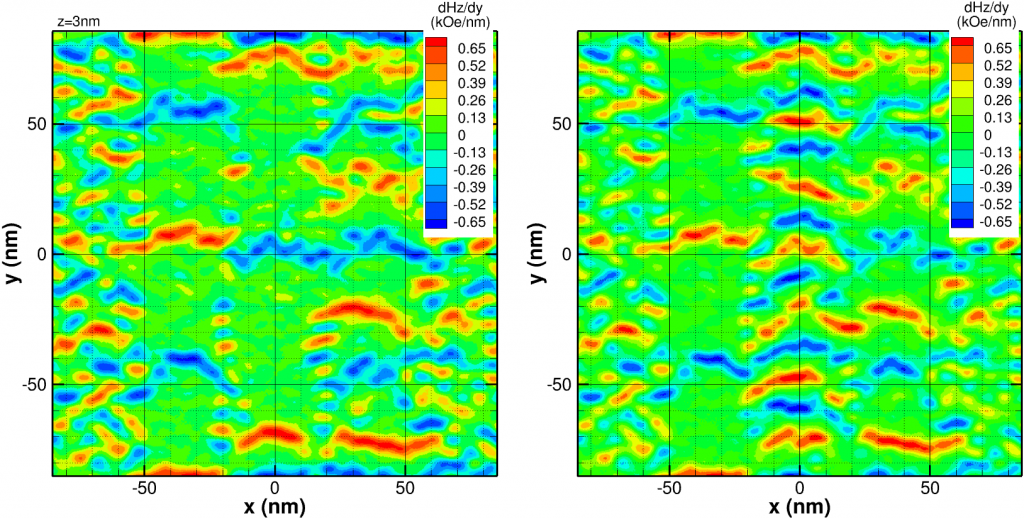
In our case, v is in the positive y direction and we take n to be the unit vector parallel to A, i.e. A = An. Then EMF = – < d (B.n)/dy > Av. Taking n to be along the y direction, we find
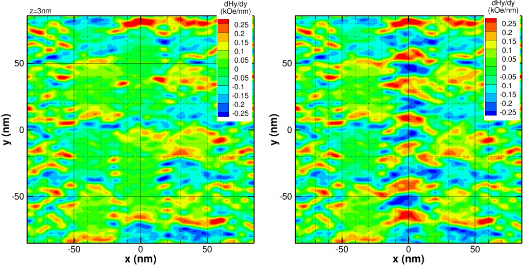
This is interesting since it implies the “transition” (where the magnetization predominately changes from one orientation to the other) is detected by a wide anti-symmetric pulse. Taking n to be normal,
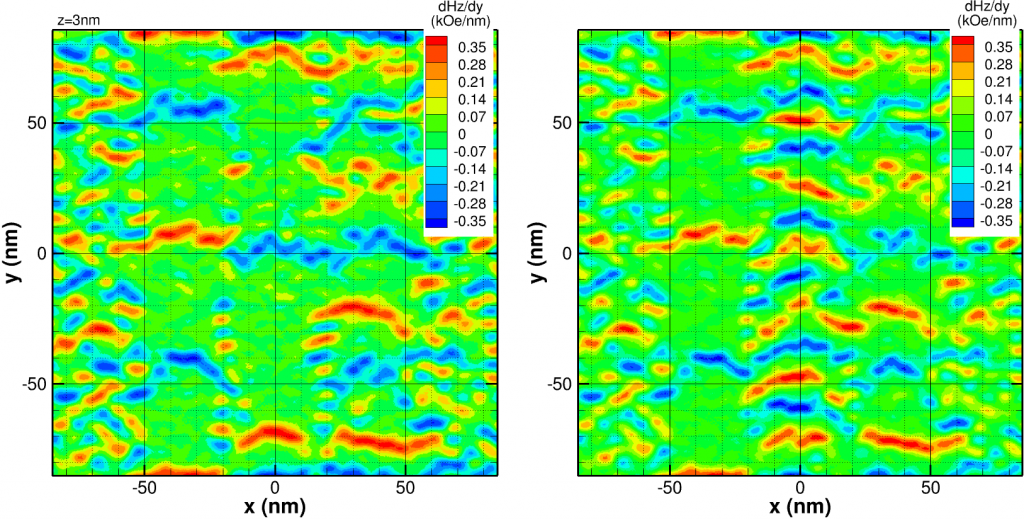
then the “transition” is now a narrower symmetric pulse (similar to old longitudinal magnetic recording of 15 years past). It is clear the maximum signal would be expected when n is normal and the loop is backed by an semi-infinite soft magnetic material:
For reasonable estimates of the cross sectional area of the loop (350nm2) and medium speed (20m/s), we estimate a peak EMF ~ 0.5 microV. Of course, this peak is directly proportional to the speed of the medium and area of the loop. The former is interesting since it implies larger signals for higher speeds, though at the cost of an higher sampling rate.
Add a Comment